Components and joints
A component is a named set of bodies: a lid, a base, a hinge leaf. Components organise a design with more than one part, hide and show a part as a unit, export it as one piece and carry it through placement. They are not a second modelling space. The design still has one timeline, and a feature in one component can refer to the faces of another.
A component stores no position. Where its bodies are is where the timeline put them.
Making and using components
Solid › Component has New Component. With bodies selected it gathers them into a component
named Component1, Component2 and so on. With none selected it makes an empty one. A body's
right-click menu has Move to Component (a component, a new one, or none), and in the
browser a body row can be dragged onto a component row, or onto the Bodies
header to leave it.
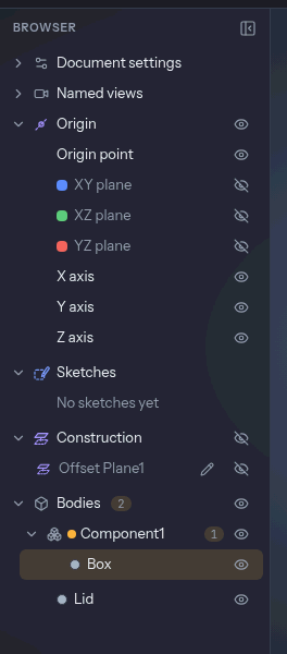
In the browser a component is a folder inside Bodies with a count, an eye and a menu. Clicking
its row selects all of its bodies. Its eye cycles shown, ghost and hidden, and the body keeps its
own state underneath, so showing the component again restores what you had. F2 renames it.
Isolate in a component's menu draws and picks only that component, with a bar over the view that says "Showing Lid only" and an Exit isolation button.
The active component
Activate in a component's menu makes it the active one: the status bar says "Active: Lid", and every feature you create from then on belongs to it. Nothing is dimmed, so the other components stay pickable and you can model in context. Deactivate from the same menu or the status bar. The active component is not saved with the design.
Where new bodies go
A new body joins the component of the feature that made it. A piece broken off a body by a cut or by Split Body joins the component of the body it came from. Anything else is loose. Editing a feature never changes the component it belongs to. Move a body by hand and the move is remembered.
Pieces and copies
- Pieces (a cut that severs a part, Split Body) stay in the component of the original.
- Copies (Copy Component, a pattern or a mirror with copies) are new bodies that follow the rule above. Copy Component makes the copy and a component named "Lid (2)" in one undo step.
Moving and placing
Because a component has no transform, Move Component is the Move tool opened with the component's bodies selected. Copy Component is the same with Create copy on. Patterns, Mirror and Scale take a component too: select its row and the tool is filled in.
Place Component on Bed (the context list on a flat face of a body in a component) lays the face on the bed and carries the component's other bodies along with it, as one.
Assembled to check, laid out to print
One timeline holds one position. To see the parts assembled and to print them laid out, put the layout at the end of the timeline as a group:
- Model the parts where they fit together.
- Add the Move and Place on Bed features that lay them out on the bed.
- Select those chips and Group them, naming the group "Print layout".
- Suppress the group to see the assembly, unsuppress it to print.
Joints are made and checked on the assembled position, so suppress "Print layout" before using them.
Export and print
The Export dialog lists bodies under their components, and a component's heading chooses all of its bodies. With Keep components together on (the default):
- a 3MF holds each component as one object made of several parts, which a slicer shows as one part with several bodies, each able to take its own filament;
- a STEP file holds each component as an assembly whose children are its bodies;
- STL has no structure, so the bodies are concatenated.
A component's menu has Export Component…. With the option off every body is exported alone.
Print Info keeps its totals and, when the design has components, adds a row per component under them: its weight, filament length and cost, from the bodies the totals count, and a "Loose bodies" row when some bodies are in none.
Joints
A joint says how one component moves against another, so you can see the motion and check its clearance before you print. Joints are as built: you pick a frame on each of two components where they already are, and nothing moves. There are three types:
- Rigid: the two move as one, which carries a part made of several components along.
- Revolute: the moving side turns about an axis, between two angle limits or a whole turn.
- Slider: the moving side moves along a direction, between two length limits. A slider needs both limits to be posed or checked.
Making one
Joint (J, Solid › Component) opens the dialog. Choose the Type, pick the Moving part and
the Fixed part (a cylindrical or conical face, a circular edge, a straight edge, an axis or a
sketch line for a revolute; a flat face, an edge, an axis or a sketch line for a slider), and set
the limits. Pick a body that is in no component and the dialog tells you to put it in one first.
OK adds the joint in one undo step. Its row sits under the moving component in the browser.
The axis or direction is read from the fixed side, and the moving side's frame has to agree with it as built. If it doesn't (a layout move has laid the parts apart), the joint shows a warning and is not posed or checked until you suppress that move.
The pose
A joint row's Pose… opens the Joint panel: a slider and an angle or travel field, with a handle in the view. The moving components (and anything a rigid joint carries with them) are drawn turned or moved, and a bar says the design is unchanged.
A pose is a look, not a change. It isn't saved, can't be undone and recomputes nothing. Posed bodies can't be picked, and starting any tool or dialog puts everything back, so you can never model against a body that is drawn somewhere it isn't. To keep a position, move the component with Move.
The clearance check
Check clearance in the Joint panel samples the joint's whole range and measures, at each pose, the smallest distance between the moving bodies and every other body, hidden or ghosted ones included. It reports the tightest gap and any collision:
- "Tightest gap 0.18 mm at 72°"
- "Collides from 64.2° to 81.0° (3.2 mm³ at 72°)"
The result is measured against a Minimum gap, which starts at the design's tolerance
parameter when it has one (see print tolerance) and 0.2 mm otherwise. Each line
has Show, which poses the joint there. The tightest pair of points gets a leader in the view
and the colliding faces turn red.
A print-in-place hinge
- Model the base plate with two knuckles and the leaf with its own knuckle between them, each as its own component, with a pin gap of 0.4 mm all round.
- Make a revolute joint: Moving part is the leaf's knuckle face, Fixed part the base's pin face, limits 0° to 180°.
- Check clearance. The result is the tightest gap along the swing. If it reads "Collides from 140.1°", the leaf's edge reaches the base plate there; give it room or limit the joint.
- Set a
toleranceparameter (the 3D Print tab's Tolerance panel) and the check measures against it, so a hinge that prints with a loose printer and one with a tight one are judged differently.
On a 130-face hinge the whole turn takes about 16 s, with progress and a Cancel button.
What isn't there
- A pose that moves the design. A joint's value never becomes a Move.
- Motion studies and animation, several joints posed at once, and joint limits that stop a drag at contact.
- Joint types beyond rigid, revolute and slider (cylindrical, ball, planar, pin-slot).
- Joints inside a nested component, and components inside components.
- An automatic plate layout. Use the "Print layout" group above.